Locating Marks for Secondary Operations

Returning to the clamp example from the previous post, let’s take a closer look at how the  bolt holes were made through the side of the clamp.

In the photo below of the two clamp halves, you will notice that the clamp has indendations along the cut line where the bolt holes go. This makes it easier for a drill press operator to precisely locate the position of the holes.

The two halves of the split clamp before the bolt hole is drilled in the cut edge. Note the indentation which indicates where the bolt holes will be located.

The two halves of the split clamp before the bolt hole is drilled in the cut edge. Note the indentation which indicates where the bolt holes will be located.

Drilling a bolt hole in the cut edge of the clamp with a drill press. The indentation in the cut line helps locate the correct spot for the hole.

Drilling a bolt hole in the cut edge of the clamp with a drill press. The indentation in the cut line helps locate the correct spot for the hole.

A similar indentation in the cut line can be used to mark the location of blind holes or other features created by secondary operations.

Custom Clamps

One common application of waterjet cutting is to make custom clamps to hold pipe or tubing in place. You can see an example of such a part in the photo below.
Note that the bolts holding the to halves of the clamp together pass through a hole in the cut edge of the part.

 waterjet cut custom clamp holding two poles together.

waterjet cut custom clamp holding two poles together.

Bending/Braking Waterjet Cut Parts

For parts where t-nut construction won’t work, you may consider bending flat parts in a sheet metal brake.
Be aware that getting precise results from bending can be difficult. There are many factors to consider, including the bend radius of the material, the amount the material will stretch, and so on. Wikipedia has a brief overview of the subject.

Typically, an experienced brake operator will perform several practice bends on test parts in order to get the setup and bending procedure just right for accurate production parts. Thus, you should have several extra parts made and plan on your final accuracy being no better than +/- 0.01 inches in a small production run. You can compensate for this inaccuracy by, for example, elongating mounting holes in the part.

If you plan to use aluminum in a part which needs to be bent, you should use 5052 alloy instead of 6061, as 6061 is prone to cracking when bent.

Waterjet cut aluminum 5052 parts before bending on a sheet metal brake

Waterjet cut aluminum 5052 parts before bending on a sheet metal brake


The same parts as above after bending on a brake.

The same parts as above after bending on a brake.


The position of the ends of the bend line can be indicated by indentations along the cutting line. In addition, the material can be made easier to bend by cutting narrow reliefs along the bend line. A drawing of such a part is shown below.


Drawing of flat  piece to be bent.

Drawing of flat piece to be bent.

The photo below shows the part waterjet cut from 0.08 inch thick aluminum. The reliefs on this piece are large enough and the material thin enough that this was able to be bent accurately by hand. For added strength, the length of the reliefs should be reduced.

0.08 inch thick aluminum 5052 piece bent (left) and original flat piece (right)

0.08 inch thick aluminum 5052 piece bent (left) and original flat piece (right)


Help Deciding on a Material Thickness

Selection_050

In a previous post, I showed you a little bit about how to choose a material. I’ve found in my work at Big Blue Saw that many people have trouble deciding on a thickness as well.

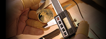
If you don’t have a set of calipers or a micrometer with which to gauge the thickness of the material you would like to use, you can use common household objects instead. Use chart below to get a feel for various thicknesses. You could also use any of these objects to measure existing parts.

For thicker measurements, stack several parts together. For example, 3 CDs are 3 X 1.2 mm = 3.6 mm or 0.142 inches thick.

Inches Millimeters
Dollar bill 0.0043 0.1092
#9 Standard Razor Blade 0.009 0.2286
#12 Heavy Duty Razor Blade 0.012 0.3048
Credit Card 0.030 0.76
CD, DVD, or Blu-Ray Disc 0.047 1.2
US Dime 0.053 1.35
US Penny (Cent) 0.060 1.52
US Quarter 0.069 1.75
US Nickel 0.077 1.95
Canadian Polymer Banknote 0.004 0.091
Canadian 10 Cents 0.048 1.22
Canadian Cent 0.057 1.45
Canadian 25 Cents 0.062 1.58
Canadian Dollar 0.069 1.75
Canadian 5 Cents 0.069 1.76

Table of material thicknesses


Exporting from 3D Modeling Tools for Waterjet Cutting

Waterjet quoting and final cutting is driven from 2D vector format files. However, many people use 3D modeling tools for their designs. Popular software packages in this category include Pro/Engineer, Sketchup, SolidWorks, Inventor, Geomagic (Alibre) Generating an appropriate 2D file generally means going though an export process to get the correct projected version of the parts to be made.

ViaCAD part export, zoomed out

ViaCAD part export, zoomed out

The biggest stumbling block here is that many 3D design tools will add perspective information, such as hidden lines, to the final output. Lines in the drawing to indicate perspective simply confuse the waterjet software. Below is an example of this problem. The original design was exported as a 2D drawing from ViaCAD (though this problem is by no means unique to that package. When zoomed out, the part looks like a simple outline.

ViaCAD part export, zoomed in on the problem area

ViaCAD part export, zoomed in on the problem area

However, when you zoom in on the upper right hand corner of the image, you can see that the software has drawn the front and back of the part in perspective, plus a middle line. The extra lines will simply confuse the waterjet software, as there is no real indication which line represents the outline to cut.

Choosing Software to Design Your Waterjet Cut Parts

Using your favorite design software

Most graphic design and CAD software allows you to export your design into a DXF format compatible with most waterjet cutting services.
Note that DXF format is a vector file format, as opposed to a raster or pixel based file format. Vector formats allow precise creation of curves, lines and other shapes. Examples of vector based desgin software include Inkscape, Adobe Illustrator and Corel Draw.

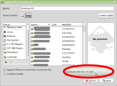
Exporting from design software that supports vector drawing to DXF is typically a matter of choosing File | Export from the menu or File | Save As…, and then picking the DXF format.

Exporting in DXF format

Exporting in DXF format

If you don’t yet have design software

If you are just getting started and don’t yet have CAD or graphics design software, don’t worry. There are many great software packages out there, all of which are free to use and are of professional quality.

1. Free vector based drawing software for Windows, Macintosh, and Linux:
Inkscape (see the note on Inkscape below)

2. Free Computer Aided Design (CAD) software for Windows:
Solid Edge 2D

3. Open source Computer Aided Design (CAD) software for Windows, Linux, and Macintosh:
QCad or Librecad

4. The Big Blue Saw Designer, an online tool for Java-enabled web browsers.

More on T-nut Construction

In an earlier post, I mentioned overcutting the inside corners of the parts so that they fit together better. Below are diagrams that show what this looks like.

Inside corner reliefs on tab section to compensate for kerf

Inside corner reliefs on tab section to compensate for kerf

Inside corner reliefs on slot section to compensate for kerf

Inside corner reliefs on slot section to compensate for kerf

You should decide whether it’s more important to have a tight fit or easy assembly.

If you go with “tight fit”, you should design the slots slightly undersized (0.005 or so), and fix it by filing away any excess. Heating the hole section with a torch or heat gun so that it expands will make putting the pieces together easier. You can force the pieces together with a press or even a hammer.

If you want “easy assembly”, you can get the parts to hold together more tightly using retaining compound (Loctite makes a good one) or epoxy.

Finishing waterjet cut parts

For many kinds of parts, the surface appearance of the part is of no great importance. For example, parts used deep inside a machine can be scratched or scuffed, and still work perfectly well. However, for many applications, having a regular, smooth appearance is important. In this category are things like car dashboard panels, musical instruments, and signs.
Several things can contribute to a blemished or uneven appearance in a waterjet cut part. To begin with, the stock material from which the part is cut may have surface scratches or marks. This is particularly true of aluminum and carbon steel plate, as these are often not considered as being for decorative use by their manufacturers. The waterjet cutting process itself can also cause irregularities. As mentioned above, parts cut on the waterjet will usually have frosting on them from stray particles from the cutting stream hitting the part.

Additionally, most parts waterjet cut from metal will have a small burr around the cut line on the bottom face. This is very undesirable in parts that must be touched or held, such as tools or handles.

.

 Parts after waterjet cutting: Stainless steel which began with a 2B finish on the left, aluminum on the right

Parts after waterjet cutting: Stainless steel which began with a 2B finish on the left, aluminum on the right

In the photo above, you can see the “frosted” areas around the part’s cut line, and the typical, slightly rough surface on the cut edge of a waterjet cut part. Parts with no finish may also have scuff marks due to handling and easily removed printed lettering from the mill that produced the raw material.
In the unfinished state, parts will typically have a small burr where the waterjet exits the part. Softer metals, such as aluminum, are more likely to have this burr. The burr can be easily removed with a sharp implement like a knife, or sandpaper. You can see an example of a burr in the photo below if you look very closely at the edge.

Closeup of the burr on 6061 aluminum

Closeup of the burr on 6061 aluminum

A waterjet cut part made from  soft aluminum showing burrs and frosting on the bottom face.

A waterjet cut part made from soft aluminum showing burrs and frosting on the bottom face.

There are several techniques for cleaning up a waterjet cut part. The simplest is sanding with medium to fine grit sandpaper. This works well on most metals, including steel and aluminum. To get the most even surface, sand in only one direction, following the grain of the metal.

A waterjet cut aluminum part hand finished with sandpaper

A waterjet cut aluminum part hand finished with sandpaper

You can remove burrs by hand using a sharp knife or deburring tool. The photos below show the process of removing the burrs from around the large circular hole in an aluminum part.

The bottom face of a part waterjet cut from soft aluminum. Note the burrs around the cut lines.

The bottom face of a part waterjet cut from soft aluminum. Note the burrs around the cut lines.

Removing burrs from the part with a utility knife.

Removing burrs from the part with a utility knife.

The large hole on the right is now free of burrs.

The large hole on the right is now free of burrs.

A faster way clean up the face of the parts and to deburr at the same time is to use a power rotary buffing or sanding tool loaded with a ScotchBrite or similar wheel. At Big Blue Saw, we call this “Basic Finish”.

This produces an even, fairly shiny finish as shown below on stainless steel (left) and aluminum (right). Like sandpaper, this process can remove all mill identification writing. It also removes any machining marks from the face of the part, including the waterjet “frosting”. Some of the deeper marks which were present in the original raw material may be deeper than  can be removed with this process.
With this treatment, burrs on the outside convex corners of your part are removed, and most other burrs are reduced somewhat. Burrs can still be left in small holes and in deep inside (convex) corners.

Parts cleaned up with a buffing wheel (Basic Finish). A stainless steel part is on the left, an aluminum part on the right.

Parts cleaned up with a buffing wheel (Basic Finish). A stainless steel part is on the left, an aluminum part on the right.

Aluminum finished with Basic Finish

Aluminum finished with Basic Finish

Stainless steel finished with Basic Finish

Stainless steel finished with Basic Finish

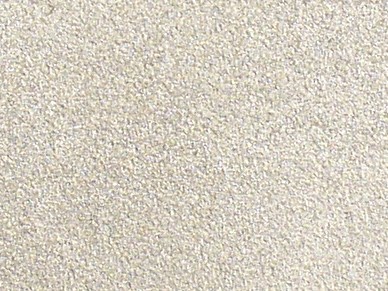
One of the best looking ways to clean up small to medium quantities of parts is through the use of sandblasting or bead blasting. In this process, the parts are placed in a sealed cabinet and sprayed with a high pressure stream of sand or tiny glass beads. Finishing through bead blasting produces a more consistent surface finish the the Basic Finish, at the expense of some shininess. All machining and handling marks will either be eliminated, or made very hard to see. It is produced by spraying the parts with a high pressure, dry stream of tiny beads. The photo below compares the Bead Blast Finish on stainless steel (left) and aluminum (right).

With this process, burrs are reduced across the entire part, but may remain if there are large burrs in hard-to-reach places.
The Bead Blast finish also gives the face of the part an appearance consistent with the edges which were produced by waterjet cutting.

 

bead blast finish

Closeup of Bead Blast on an aluminum part

Closeup of Bead Blast on an aluminum part

: Closeup of Bead Blast on a stainless steel part

: Closeup of Bead Blast on a stainless steel part

Waterjet cutting for gears

Traditionally, spur gears are made using specialized tooling and setups. This means that small runs of custom gears can be expensive; much more expensive than most other types of machined parts.

However, the flexibility of a waterjet cutting machine means that gears are no more difficult to waterjet cut than any other part. At Big Blue Saw, we have made many gears for customers who needed unusual sizes of gears or gears with custom mounting holes. Other customers have wanted, for example, polycarbonate plastic or titanium alloy gears which were impossible to find off-the-shelf.

 Steampunk costume by Chris Lee with waterjet cut aluminum gears which actuate a set of wings

Steampunk costume by Chris Lee with waterjet cut aluminum gears which actuate a set of wings

 Steel (left) and aluminum (right) gears

Steel (left) and aluminum (right) gears

Waterjet cutting works best with gears of 12 diametral pitch (DP) or larger. As you can see in the diagrams below, the waterjet cutting stream is small enough to easily machine the features of this size gear. Additionally, a geartrain of this size or larger can tolerate the roughness of the cut edge on a waterjet cut gear. With a waterjet stream diameter of 0.04 inches, however, you can make gears down to about 20 DP. I would only recommend this size for thinner gears in applications where there is some “slop” in the geartrain due to the surface roughness of the cut edge as well as other irregularities which can arise from waterjet cutting.

Waterjet stream of  0.04" diameter shown with a 12 DP gear

Waterjet stream of 0.04″ diameter shown with a 12 DP gear


Waterjet stream of 0.04" diameter shown with 16 DP gear

Waterjet stream of 0.04″ diameter shown with 16 DP gear

 Waterjet stream of  0.04" diameter shown with a 20 DP gear

Waterjet stream of 0.04″ diameter shown with a 20 DP gear

 Waterjet stream of  0.04" diameter shown with a 24 DP gear

Waterjet stream of 0.04″ diameter shown with a 24 DP gear

Waterjet cut gears are rough along the cut edge where the gears mesh together. This can cause a shorter gear lifetime due to wear than you might expect from a traditionally cut gear. So for applications where this might be a problem, you should consider making the gear larger, either by making it from thicker material, or decreasing the DP so that the teeth are larger.

When first using new waterjet cut gears, it is a good idea to let the gear train run continuously for a few hours without load and with a light lubricant. Then clean the gears and re-lubricate before placing the gear in service. This will even out the rough cut edges of the gears and allow the geartrain to run smoothly.

Gears above 1/8 inch (3 mm) thick should usually be cut using low-taper cutting. This allows waterjet cut gear to mesh as accurately as possible.

Some people have reported success with regular (non-low-taper) waterjet cut gears by placing two waterjet cut gears so that their tapers face the opposite directions. In other words, the top face of one gear will be on the same side as the bottom face of its matching gear.

Simplify lettering and signs by using the right font

In the last post on making signs, we saw that it was possible to make a sign with lettering in four different ways.

When you want the sign to be one piece, it can be tedious work to generate all the necessary bridges. This is true both when the letters are positive space (solid material) or negative space (holes). Fortunately, by using the correct font, you can save time and get a result that looks good.
When the letters form positive space, one good choice is to use a script font.
In the example below from David Kaufman, the Santa Fe script font was used to design two nameplates which were then waterjet cut from 1/4 inch thick aluminum. The right hand side of the “f” had to be modified to connect with the “m”, but the rest of the letters naturally run together with this font.

Nameplate signs from David Kaufman

Nameplate signs from David Kaufman

The font used in the examples above: Santa Fe LET http://www.fonts101.com/fonts/view/Script/28879/Santa_Fe_LET

The font used in the examples above: Santa Fe LET


When the letters are negative space, you can use a stencil font. Below are a few examples of the varieties of stencil fonts which might be useful for your project.

 Bodoni Becker Stencil Bold http://www.fonts101.com/fonts/view/Uncategorized/43971/Bodoni_Becker_Stencil_Bold
Bodoni Becker Stencil Bold
Tomorrow People. Note for this font: some numbers and symbols may not have appropriate bridges in this font. http://www.dafont.com/tomorrow-people.font

Tomorrow People. Note for this font: some numbers and symbols may not have appropriate bridges in this font.