I finally decided in 2023 to switch brushless drive in Flipper 720, my robot competitor at Dragon*Con Robot Battles. I felt it was time to get with the modern world and add a bit of power to my robot while I was at it by moving away from classic brushed motors. Unfortunately, I found out that running brushless motors in a fighting robot is really a lot less straightforward than brushed motors, where there are many more plug-and-play options. Are brushless and mistake synonyms, as some have suggested? Read on and find out.
I kept a log on Facebook of mistakes I made over the course of 6 months in hopes that I could pass along some wisdom to other builders. This blog post is a collection of those log entries, edited and updated for clarity and continuity.
The earliest mistakes came from reading old or obsolete information on the internet, of which there seems to be an abundance. I don’t want to call out anyone specifically, but many popular websites, posts on Facebook groups, replies to my posts, etc. give info about technologies that are obsolete, or products that are no longer made. It’s hard to separate the gold from the slag. Thus, I ended up buying one motor controller that doesn’t make sense for robot fighting because: 1. a similar model was recommended on an old list of speed controllers 2. nobody told me there were better options when I asked on a Facebook group.
Now, buying a useless speed controller isn’t the end of the world. I consider this kind of thing a reasonable expense for R&D and it can always be used for testing or other applications. But I do wish I could have that time back that I spent on buying, researching, and setting it up.
So, on to motors. When you put together a brushless motor system, you’ll have to decide between the outrunner and inrunner types of brushless motor. I’m not going to get into the details here on what the difference is. But I found an outrunner motor that seemed like it would work and ordered that for testing. When I got it, it turned out there were 2 things wrong with it:
1. The long end of the shaft came out the wrong side of the motor, the moving side instead of the stationary side. Some outrunners are built this way and some aren’t. This is probably fine for drone use, but impossible if you’re plugging the motor into a gearbox. With some of them, it’s possible to swap the output shaft around so that it comes out the other side. But I never got around to that because:
2. The output shaft was the wrong size, 5 mm instead of 3.175 mm. You see, I was attempting to replace 550 motors, which have a 3.175 mm output shaft, going into BaneBots gearboxes. Now, the BaneBots input pinions can be ordered with a 5 mm bore, but for certain reduction gearboxes, the pinion is too small to support the 5 mm bore. I don’t want to switch gear ratios because of the robot’s wheel setup: small wheels in the front and big wheels in back. The wheel sizes and gearbox ratios are set up to work out pretty well.
So, eventually I landed on switching to inrunners.
I also learned that the 4 digit “model” on inrunners USUALLY represents the diameter and length of the motor can. USUALLY. So a 3660 with a 3.175 mm shaft is close to a drop-in physical replacement for a 550 motor.
I found some on AliExpress that looked could be a suitable replacement.
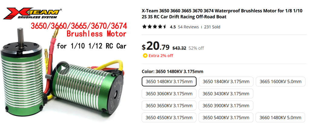
The advice I followed on these was to buy the lowest specced Kv that will accept the voltage coming from the batteries. I ordered them on March 14, and they arrived from China the first week of April.
Back to controllers. At this point I had a couple motors that aren’t right and a motor controller that’s unlikely to work. Then I spied a post from Derek Tran showing off his new drive system for a 30 pound bot. What caught my eye was the video of him fighting against and stalling the motor and the motor continuing to fight back. See, my main concern with going brushless has always been getting enough low-end torque. Those quadcopter guys don’t give a damn about low-end torque as their props happily spin up to a few thousand RPMs before they start to hit any drag from the air.
Turns out that there’s a new firmware game in town, and unlike the old standard Simonk firmware, it’s under active development. It’s called AM32 and apparently uses a bunch of new tricks to tease low-end torque out of a sensorless brushless motor. And it’s written by a hacker who only goes by a handle, like in the old days.
I ordered the motor controllers (NeutronRC 70A-G071) that Derek’s using off of AliExpress. They’re pre-flashed with AM32, so I figured that would save me some time.
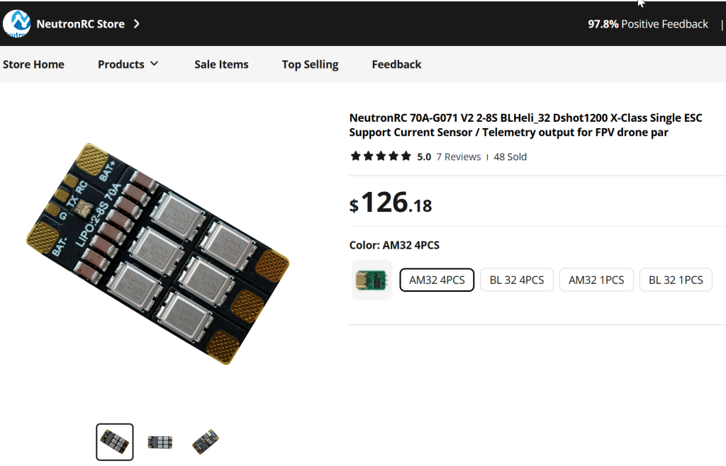
These things made their way over from China, and I figured they’re ready to go. But first, because there’s no preexisting terminals or pins to plug into, to use them you’ve got to solder at least 7 wires onto each board: 2 for power input, 2 more for signal & ground, and finally 3 for the motor output power. So back to Big Jeff’s to order a bunch of servo extenders to be cut down for their socket ends and soldered onto the board.
One time saver was that I only had to solder the signal and ground wires, and not the +5v power on the socket or the motor controller’s telemetry. Anyway, if you’re stripping servo wires, do yourself a big favor and invest in a good wire stripper. I tried using my mid wire stripper on one set of leads before running to Home Depot and getting a good made in USA Klein stripper. Made a much cleaner strip and left all the strands intact and straight.
Also, don’t use too much solder on those tiny servo wires. Just enough to coat them. Probably fine gauge solder would work best, but I didn’t have that.
One more tip on soldering: get yourself some sort of helping hands/soldering vise setup. I have perversely resisted doing this for many years, being stuck on doing things the hard way. But with this project and its tiny wires, it was time to buy one of those squid looking helping-hands stations. I got one with a magnifier, flashlight, and 4 clips on the arms. Definitely made my soldering much better.
I soldered connections on and plugged the NeutronRC into the robot. I hooked it up to one of the outrunners I bought. When I switched it on, the motor made 3 tones and moved a bit while the sounds play. But I got no control from the radio. The motor refused to go, whatever the stick position. I checked out the receiver, and it ran a servo just fine on that channel. I swapped the motor for a tinier one, with the same results. Why was my motor not turning?
It turns out that the ESCs have to be calibrated first before they’ll send power to the motor. This problem is solved by wiggling the transmitter joystick back and forth to its limits until the light on the motor controller turns green.
I got the outrunner I was testing with to turn so fast the sticker on the can of came detached and made a hell of a racket. Unfortunately it only ran in one direction.
I didn’t know, but should have guessed, these ESCs are set up out of the box to run a propeller, which only ever goes in one direction. To fix this, you have to re-flash the controller with some new settings. If you don’t have a controller with AM32 already installed, you’re in for another set of hoops that I’m glad I didn’t have to jump through, which is to install a new bootloader on the controller.
I was panicking that I would have to solder new leads onto the tiny unlabeled programming pads on the Neutron RC speed controller just to re-program the controller to go both directions. Fortunately, Lucas Grell pointed out that you can re-program it with new settings right through the servo port. Typically, this is done with a specialized USB to servo adapter, with the whole thing plugged right into a desktop computer. BUT it turns out you can also do it with an Arduino instead. And so I busted out the Arduino UNO that I had in a box for years that I intended for a long-forgotten project, but never used.
The AM32 wiki has some instructions that vaguely point in the right direction, but are missing some important details. For one, it’s based on using the older BLHeli software to program the Arduino to the USB-servo link. So the menus and options shown in the wiki aren’t quite right.
For another, it makes the assumption that you’ll be using an Arduino Nano, not the UNO like I have. After much mucking about, and examining source code it turns out that you need to use pin D11 as the output on the UNO, whereas the Nano uses pin D3.
It’s also not totally clear from the wiki, but you need the software called “Multi ESC Config Tool” where you actually modify the settings and upload the configuration to the ESC.
From the Multi ESC Config Tool, you can set the motors to run bidirectionally, among other useful settings. Derek recommended the following settings:
- sinusoidal startup off
- bi direction on for drive
- bump the timing
- stuck rotor protection off
- stall protection on
Jamison Go said that current limiting is your friend, but Derek says that many ESCs don’t have this calibrated correctly. I planned to play with that, overheat protection, and braking settings in the Multi ESC config tool, but never got around to it.
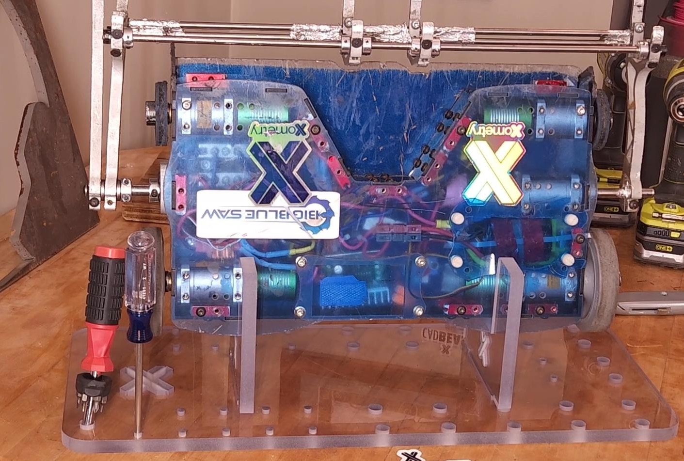
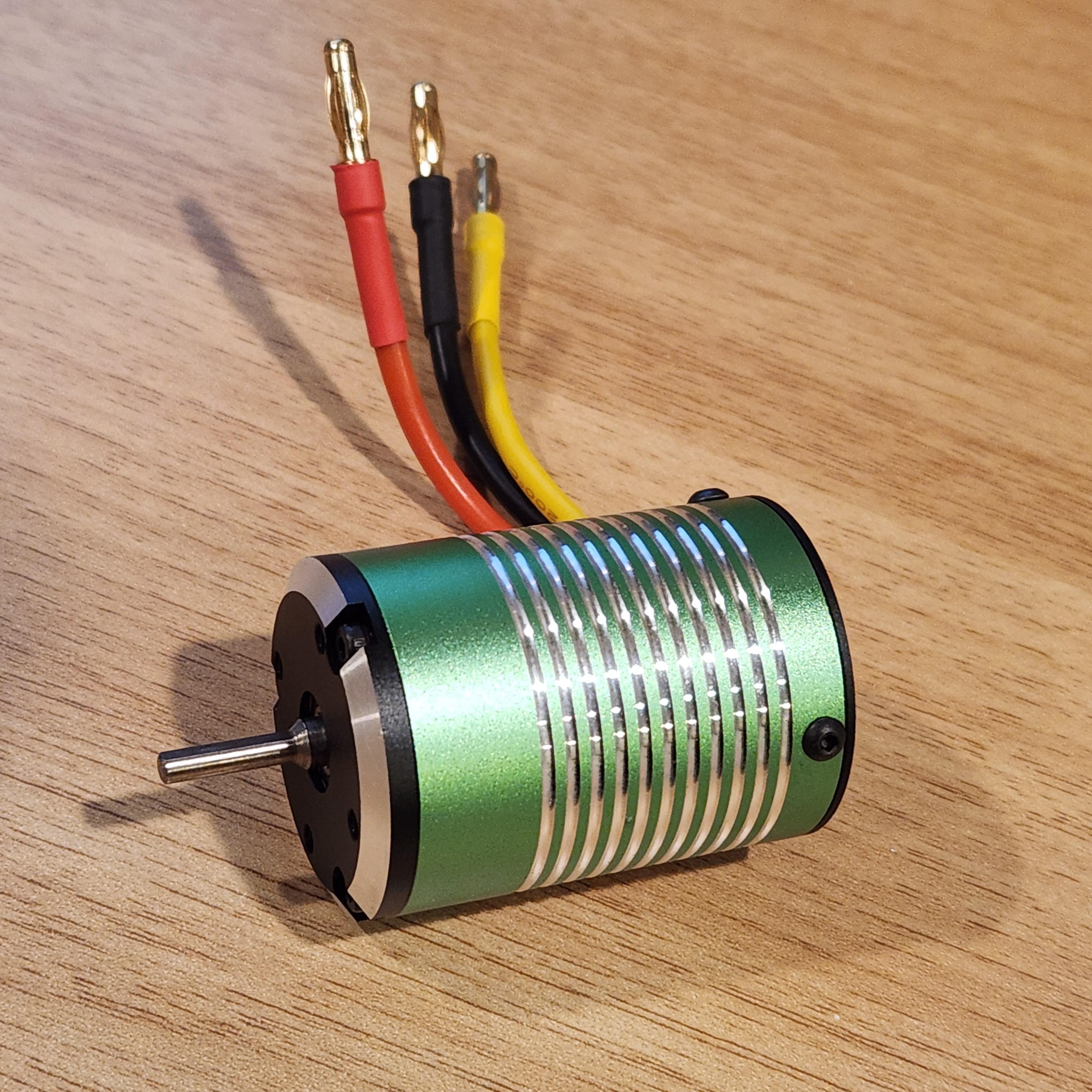
Once the motors arrived I was taken by the fact that they’re the nicest LOOKING electric motors that I’ve ever owned. Take a look at these things: clean anodized can, machined fins, and excellent fit. They even matched the heat shrink color to the wire.
The problem that I ran into right away is that they have 4 mm bullet connectors installed, whereas the first test motors I bought use 3.5 mm bullet connectors. So, after more ordering, de-soldering, and re-soldering, I finally got the new motors hooked up. I plugged one in and it worked right away.
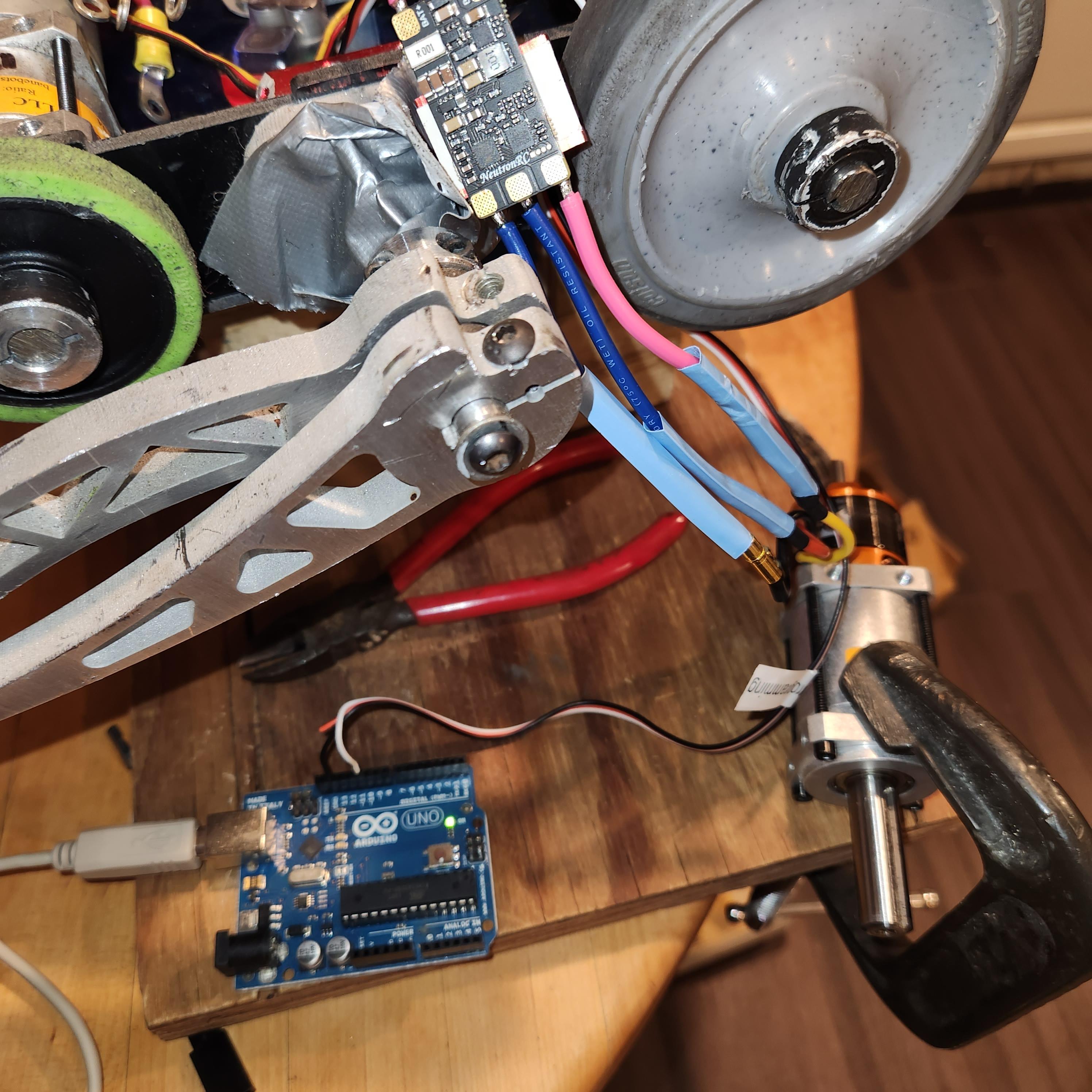
The next step was getting the motors attached to the gearbox and installed in the robot.
And… it works!
Ridiculous power. Some trouble with the motor controllers starting consistently, perhaps due to a bad cable? I never did get this fixed, and the best solution I came up with was to turn the robot main power on and off a couple times. Then all the motors would come up. The motors turned, but I needed to set up my new transmitter to make them go in the right directions. The right side motors were turning opposite directions, but fortunately switching a pair of motor leads on one of them fixes that!
At this point I took a some time off robots building to build some bookshelves, as Robot Battles was at that point off in the distant future. Taking a couple months off didn’t hurt me terribly, as what was left was mostly just mounting the controllers to the frame and plugging the wires in. I even attempted to do a proper job routing the wiring for the first time in my life.
One of the signal wires was messed up because of bad soldering on my part and cuts out if the wire is at a bad angle. I ordered 4 replacement controllers in case some decided to blow up.
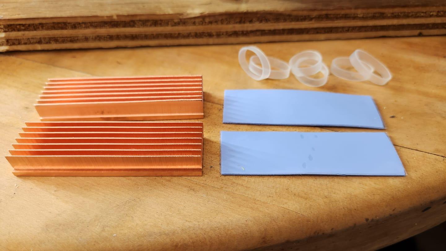
I was still worried about these tiny ESCs overheating and catching on fire, especially considering how small the stock heat sinks were. So I also ordered some copper SSD heat sinks from Amazon to replace to puny stock aluminum motor controller heat sinks.
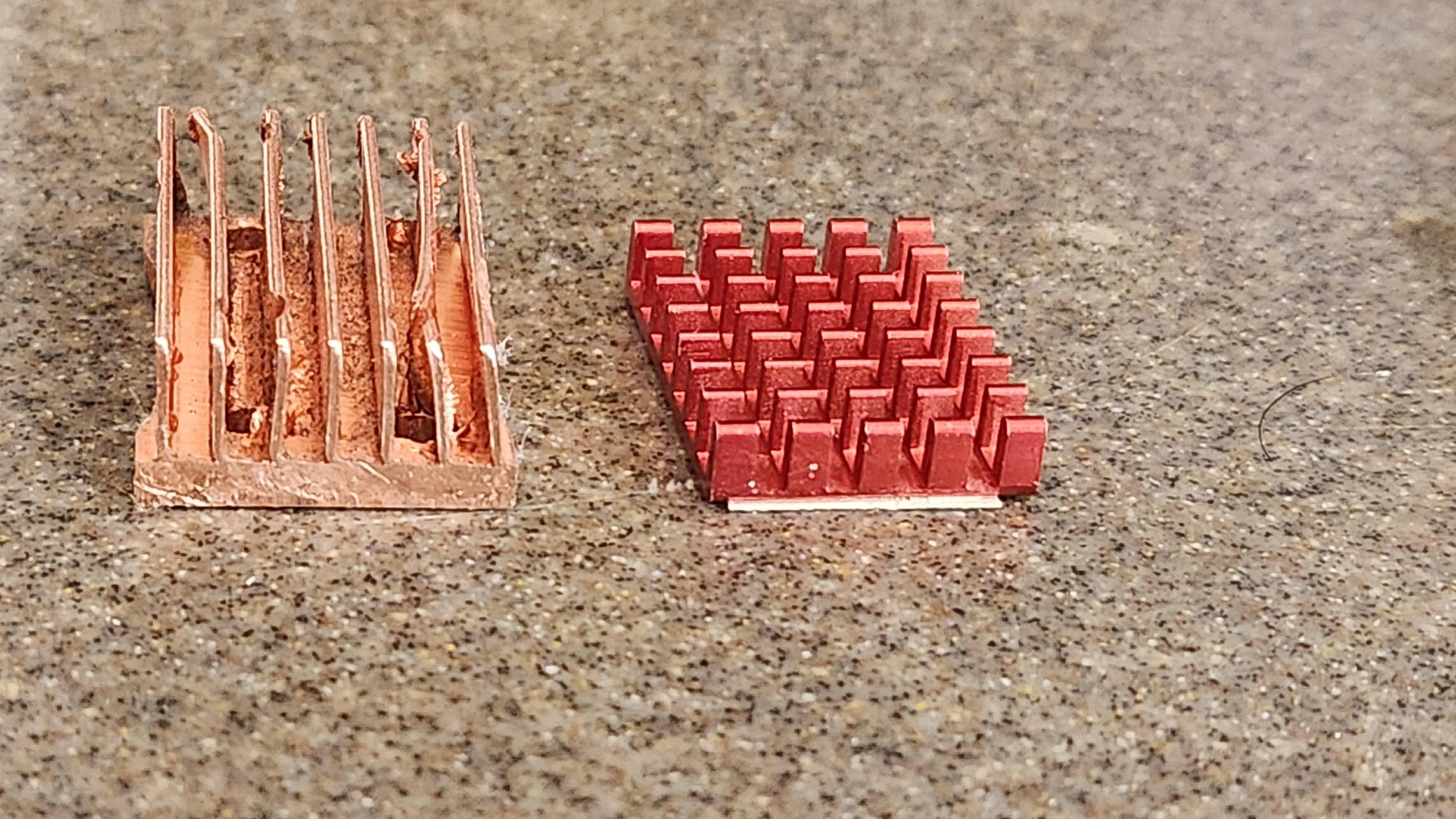
Copper heat sink compared to the stock red anodized aluminum ones.
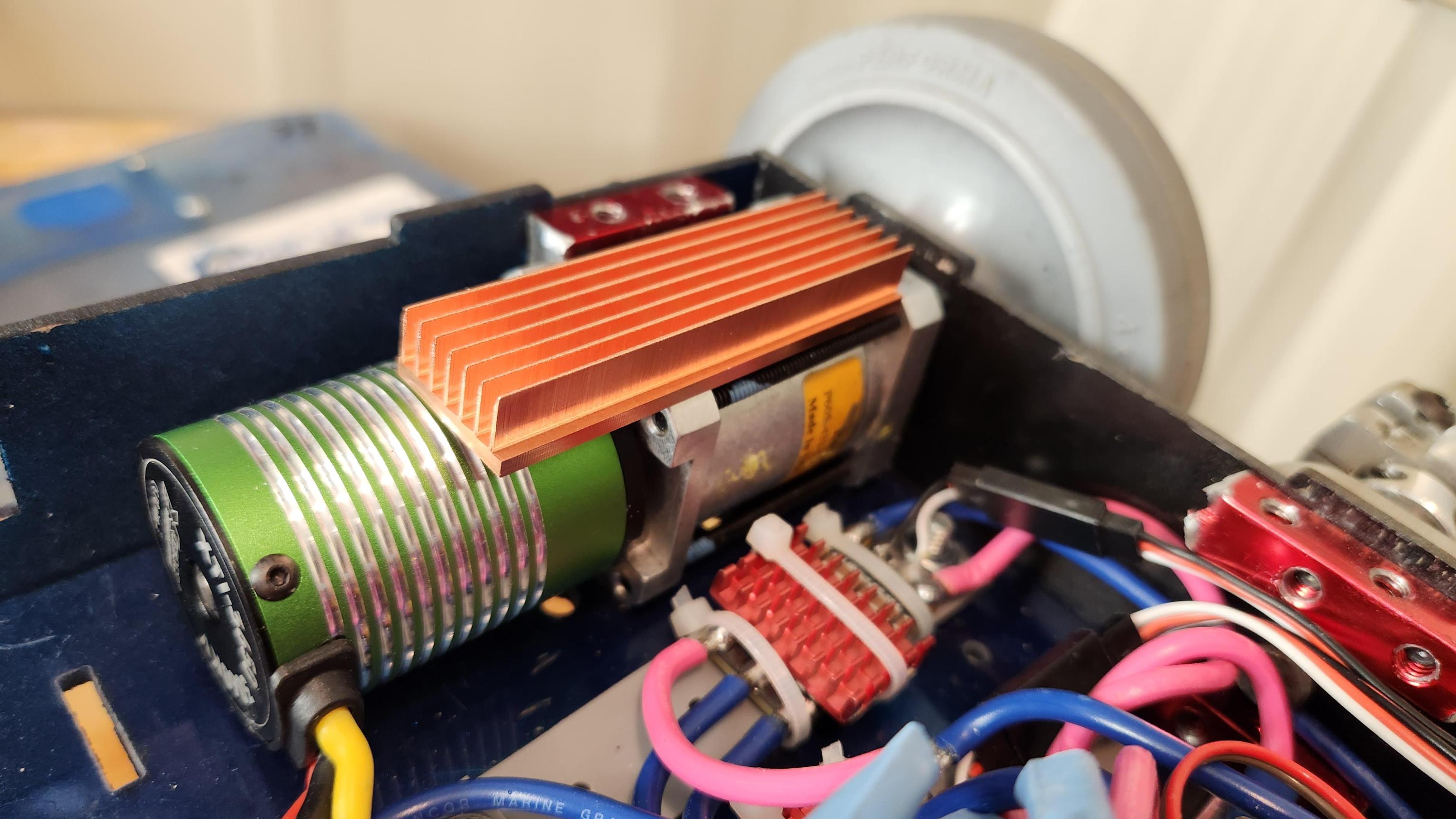
With everything in place, it was time for a real test.
Heat sinks and motors were hot to the touch with a full battery’s worth of hard driveway testing, but no smoke came out.
On to Robot Battles 72, Labor Day 2023.
Aside from the aftorementioned startup problems, the motors and controllers performed admirably.
Unfortunately, I was outdriven by Charles Guan and Testbot in the first round. But hey, I got a chance to get some revenge in the rumbles…
But drove us both off the stage.
Anyway, the motors have more than enough power now, and nothing caught on fire. My biggest limitation now is traction. I stripped the rubber off of two of the small front wheels down to their plastic hubs. Next year, I’ll need something wider and more durable.
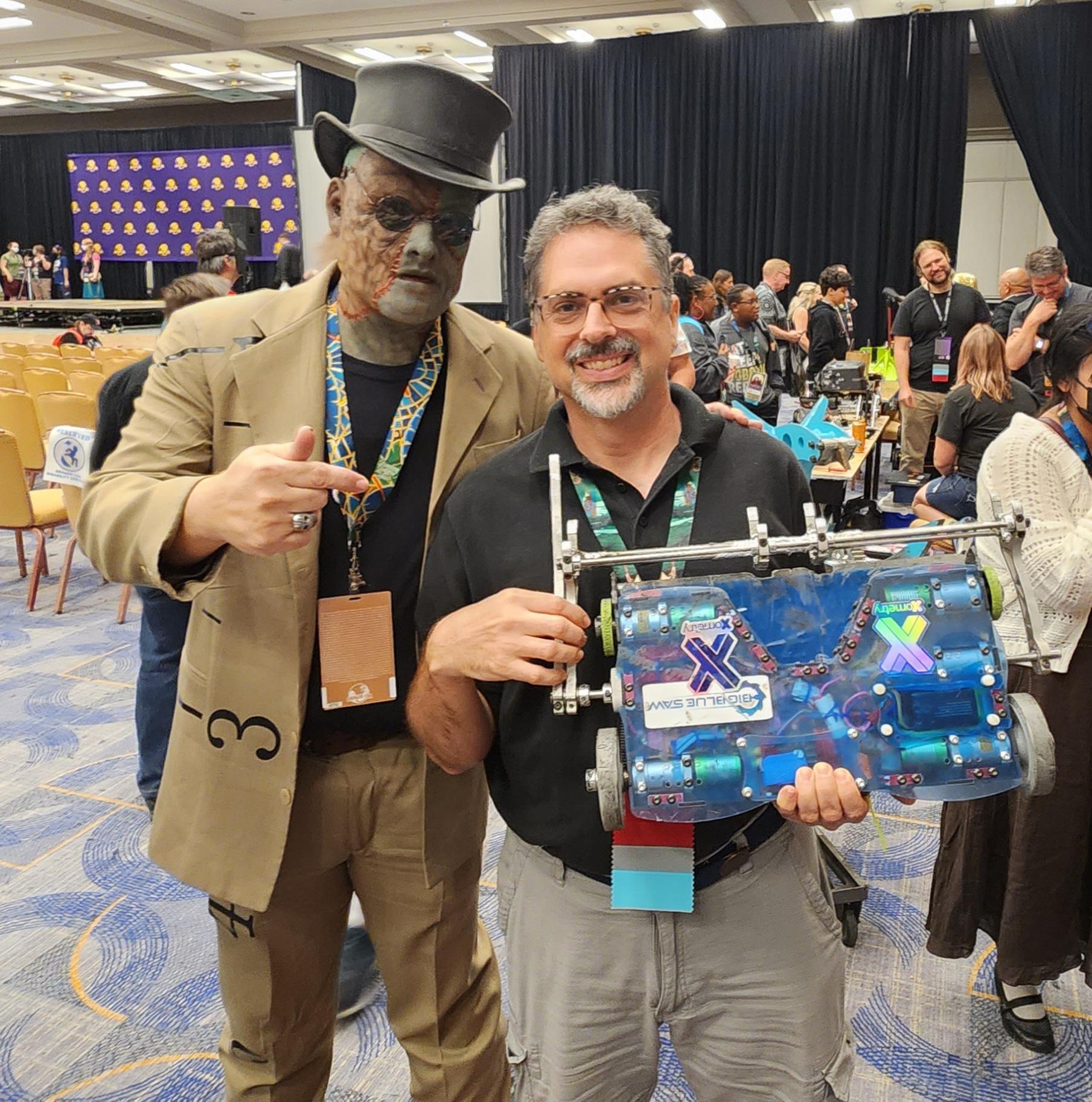
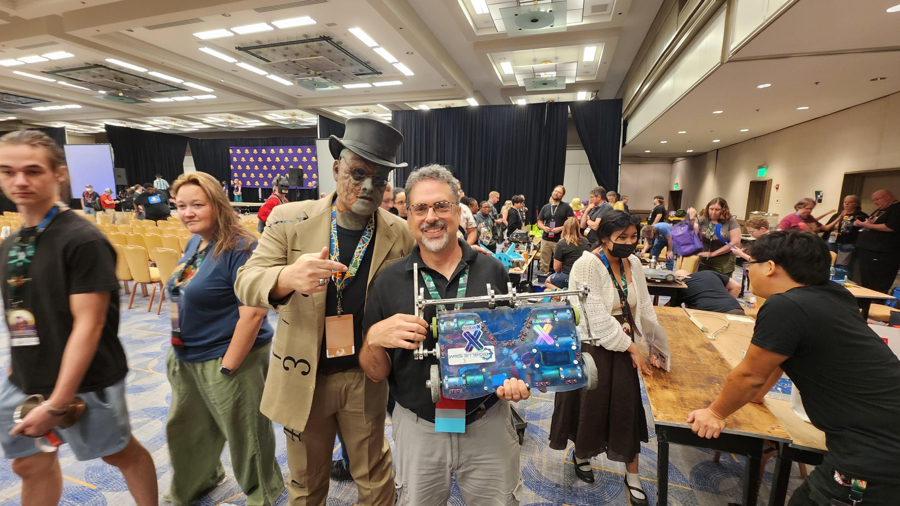
At the conclusion of Robot Battles 72, I was super happy to have my photo taken with “Frankenstein Rule”. Perhaps the first ever cosplay of a Robot Battles rule!

Hopefully, I’ll have the traction problems solved next year, and have more driving practice, to boot.